Week 6, Assignment 6
Electronic Design
Goal
This week was dedicated for Electronic Designing and components learning and usage. I am not from the background of Electronics and have never did any such hardcore Electronics work, Electronic always only fascinated me with Soldering part never went beyond that, but this assignment actually made me learn so much about Designing Electronics Circuits that to using various software’s, gave some good knowledge of different components, etc., I enjoyed and learned from this assignment a lot.
The Goal for this assignment was to Design a Circuit board with at least one LED and one Button. Prof. Neil Gershenfeld explained about various electronic components which we were supposed to use in this assignment. While searching on internet about components I got a very describable page with almost thing one should know about Electronics Components . So in this assignment we were also suppose to design circuit using more than one software for better understanding. So basically this assignment begins with redrawing the hello.world.circiut board with at least a LED and button.
123D Circuits:
I began this assignment with using 123D Circuit for designing my board. 123D Circuit is a very good and very simple to use and learn for beginners like me. We just need to drag and drop our component and then connect it accordingly. The software seemed bit easy to operate but its component search tab is not good, even after searching with the exact name I was suppose to scroll the whole list and search for what I need, but the good thing in this also was that there were good brief description about all components which I was using. Best thing was that the design was automatically getting saved online for which I wasn’t worry about then. 123D Circuit also gives real time simulator where I can prototype and design before getting the circuit even ready. Another good feature was it also has an Arduino Programming and Simulating facility available, these all made me feel good about this software; a beginner like me can find such thing easily in just one place with ease to use too. So finally with all the ease of circuit designing with this software I was able to make first the Schematic View of the circuit.
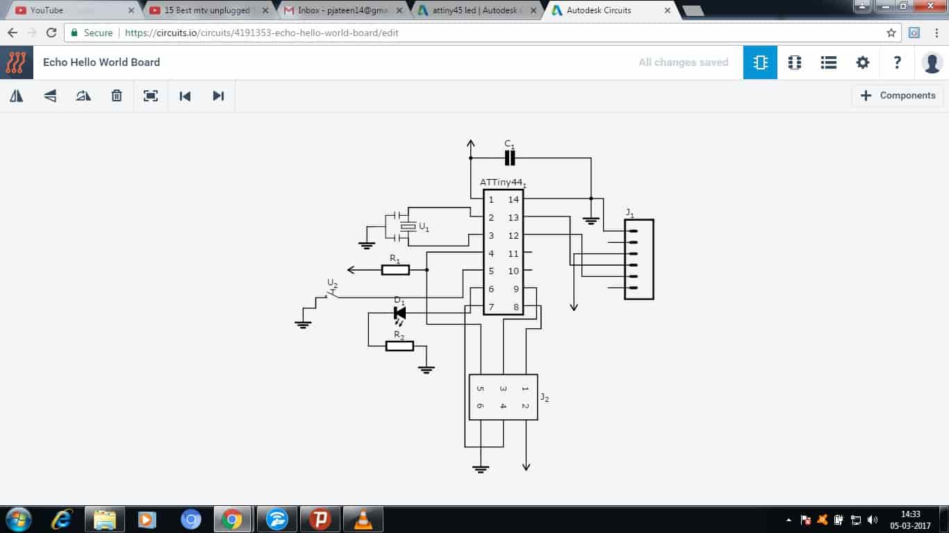
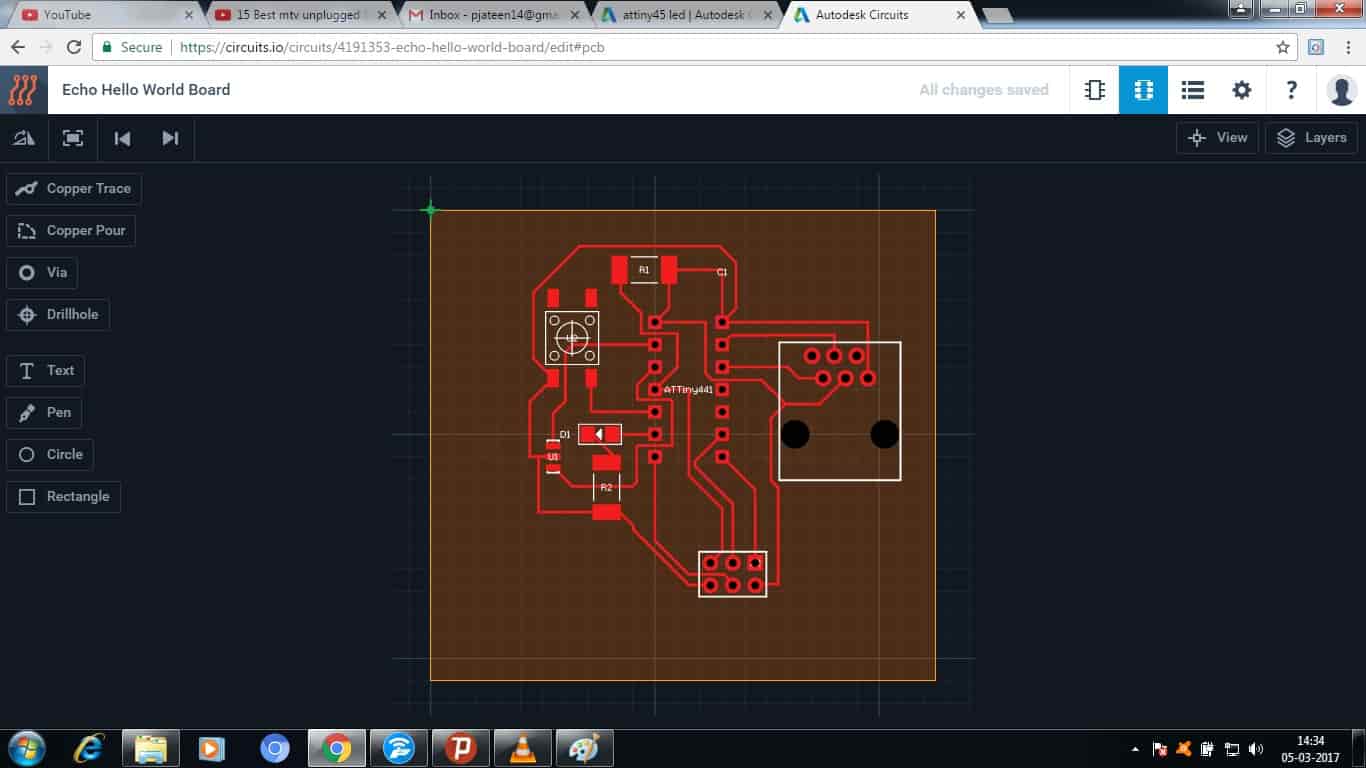
With all the ease of adding the component and just connecting them in the Schematic View, all my time went then was in PCB View of the circuit where after schematic I was suppose to make tracks of all the components with each other so that there doesn’t get short anywhere, and literally it was like solving a puzzle, it took most of my time but finally after a long work I was able to solve that puzzle and made the PCB View.
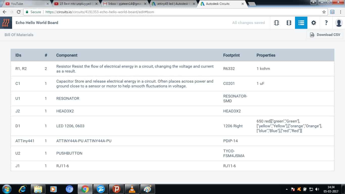
Another good thing about 123D Circuits is that it gives us a proper Bill of Material also with all the Description about every single component I used in this Circuit.
Kokopelli:
I then started using Kokopelli for designing the circuit which I was making. Kokopelli, unique name, was very interested to know the meaning of the word, so with just a little bit of searching I found a page with all the details of Kokopelli. So, Kokopelli name was given to a humpbacked flute player, considered as a Fertility Deity.
Kokopelli software is developed by Neil Gershenfeld for making circuit boards designs. It uses a coding environment having an output window for showing a graphical representation of codes. The Installation a guide with all other details of Kokopelli is given below:
So again as I am not at all familiar with even Circuit Designing, before starting to use this I went through the tutorial first and then started with its installation. To begin with installation I was first supposed to download the Python Script for my Laptop, the command for installation is given in the tutorial so I picked it from there and run it.
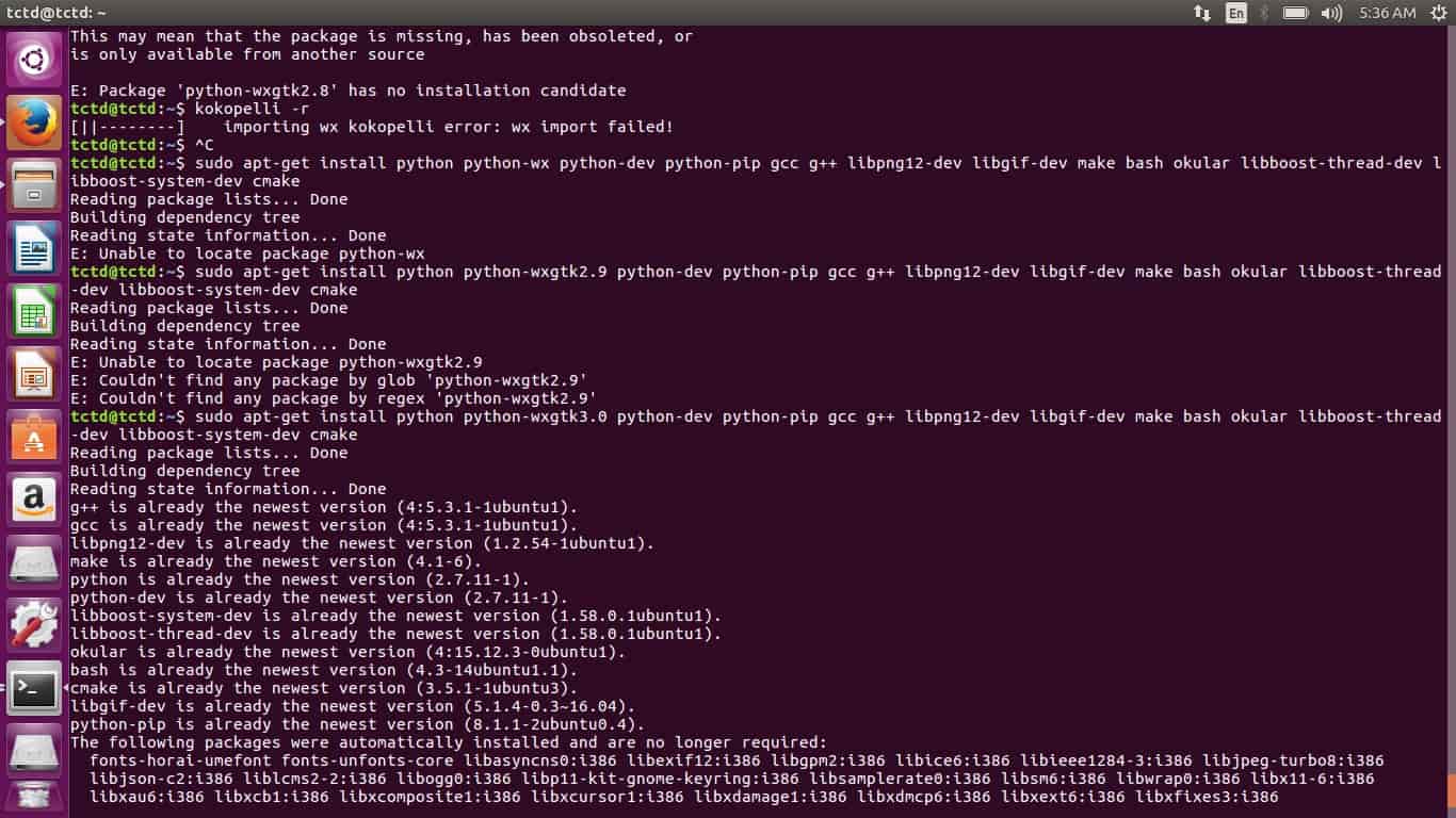
sudo apt-get install python python-wxgtk2.8 python-dev python-pip gcc g++ libpng12-dev libgif-dev make bash okular libboost-thread-dev libboost-system-dev cmake
But the after using this command I got an error as shown below:
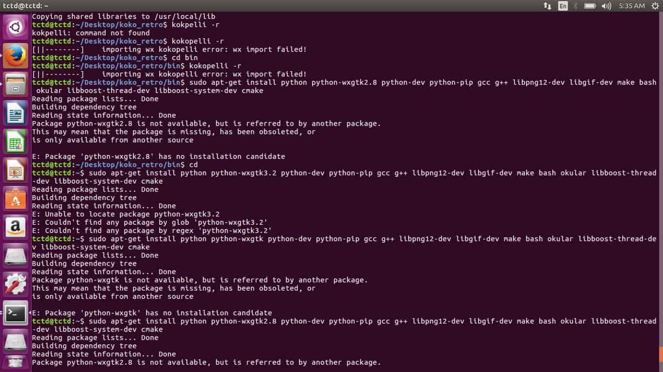
Then I did some changes and run the command again 2-3 times then I found that the error was of the older version of the Python Script, so, instead of “python-wxgtk2.8” I typed “python-wxgtk3.0” which worked very well and Python got installed.
Then to install numpy following command was used
sudo pip install numpy PyOpenGL PyOpenGL_accelerate
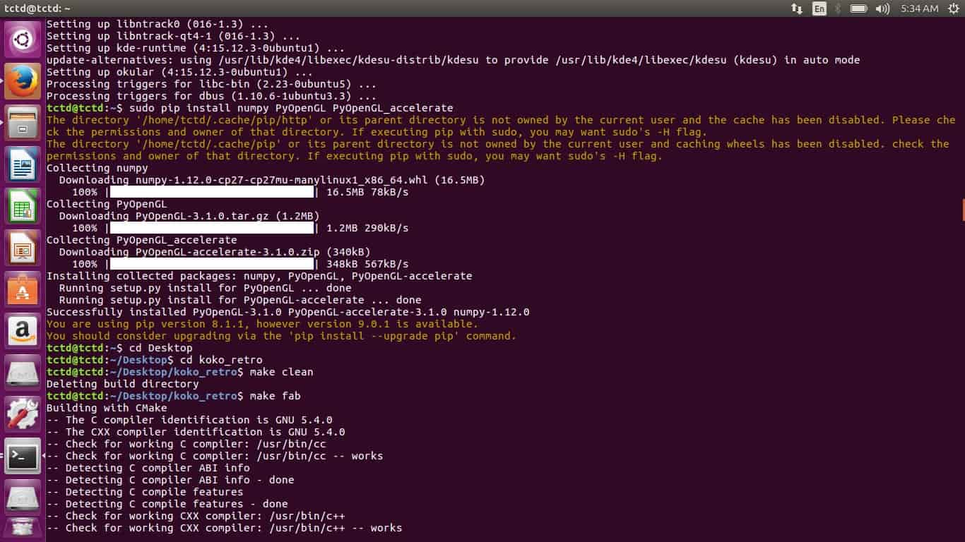
After that I downloaded the koko_retro zipped file and then unzipped it using the terminal window and browsed inside the folder and used the command:
Make clean
Make fab
Sudo make install
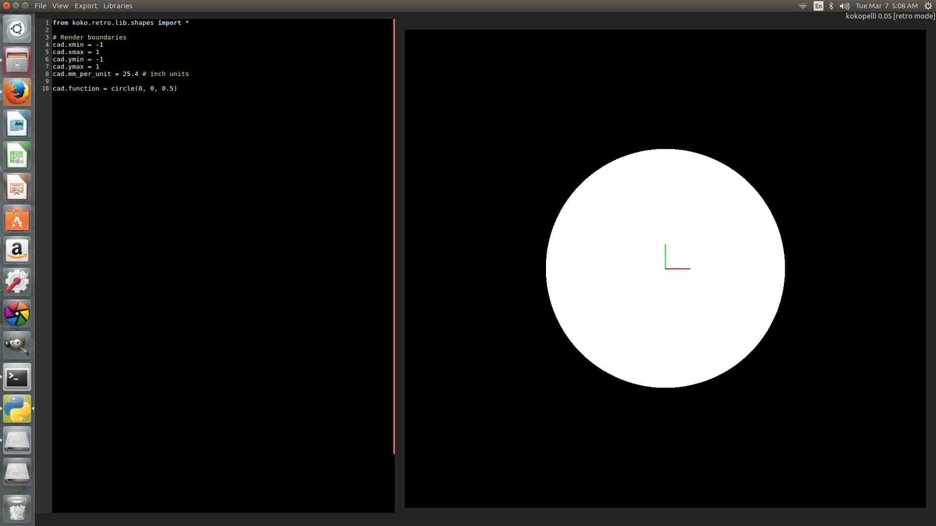
Kokopelli –r
Finally after that if all the command works properly Kokopelli gets started and I was able to see a big white dot on the screen which indicated it was installed properly.
Getting Started with Kokopelli:
To get familiar with Kokopelli I took the board which I got from Fab Academy’s this week class page.
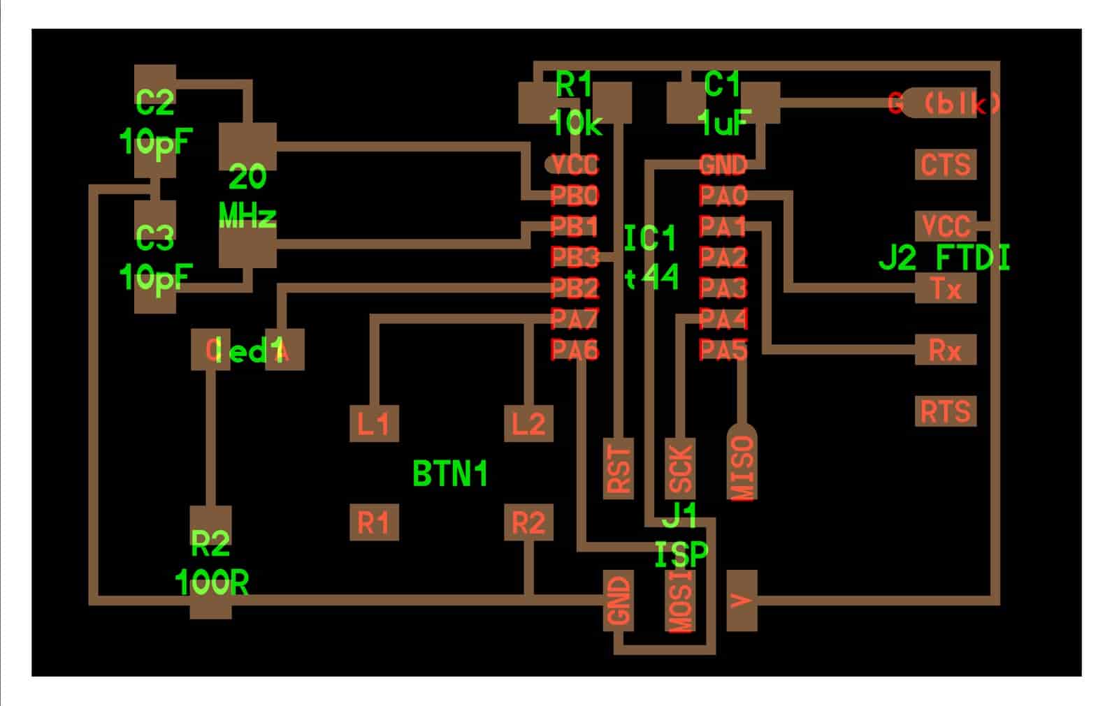
I changed resonators to Crystal Oscillator as I was running out of resonators, so added two extra capacitors as it was necessary with crystal.
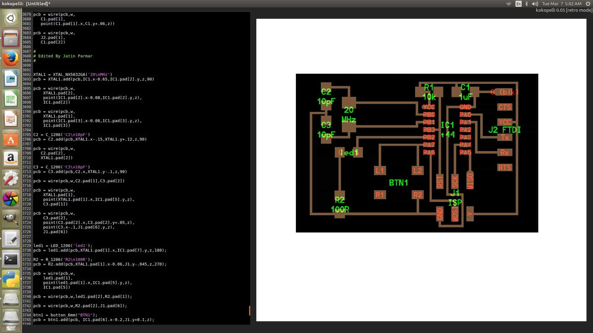
As I opened the “.cad” file in kokopelli I got all the codes used for various components, like resistors, IC’s, capacitors, LED, etc. Just I need was to search for the components code in the 4000 line coding script and put it in the exact place where I wanted it to be. First I began editing the board by changing the width and height so that I can get space to add more components which I need to.
I started adding the components with adding button first, so I searched for button code in the whole coding script and as I was using 6 mm of dimension button I added it by using the code below;
class button_6mm(part):
To make changes in the code, change the name of the component which I was using, I used the following code;
mybutton = button_6mm('My\nButton');
After doing so I wasn’t able to see the changes on the board until I defined the parameter and position the component which I was adding, to do so I used the following code;
pcb=mybutton.add(pcb,x,y,z,angle=0)
Similarly I added other components by searching and entering the various codes I needed there to be in the Board. Finally after adding and arranging I got the board like this,
Proteus:
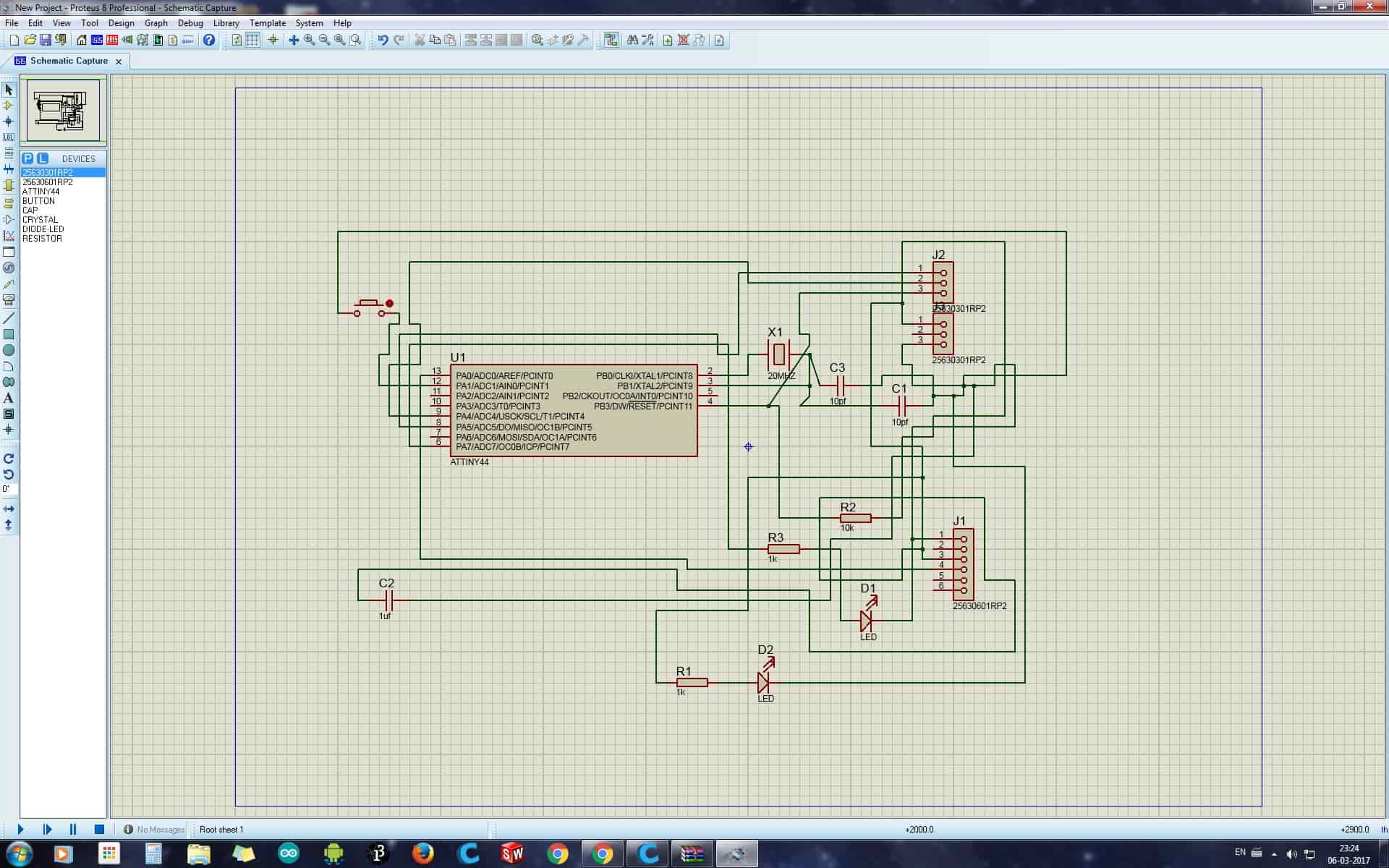
I then Started using Proteus but then just made the Schematics of the board in this, the software is very simple and easy to use, just we have to drag and drop the components and joing it accordingly.
Eagle:
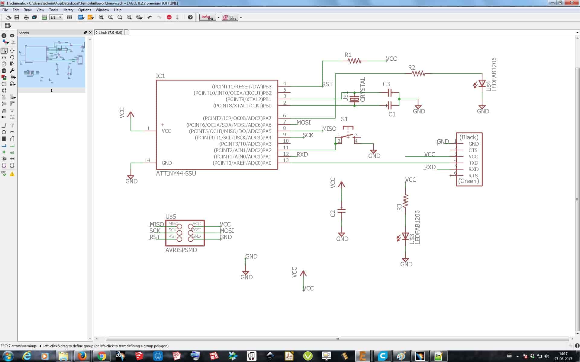
As I was new to this software too I went for some tutorials on Web and then started making the board in Eagle. First I downloaded and added fab.lbr library in the software and updated it, so that all the components I needed should be there to drag for connections. Then I started a new project and dragged all the components I needed beginning with ATTiny 44, Resistors, Capacitors, LED, Push Button, etc. and started connecting them according to the circuit. In this also as I didn’t had a Resonator I replaced it with Capacitor and Crystal. After making the Board File, I then switched to PCB Track making file and started arranging them or can say started solving the puzzle. Basically I arranged them so that I can easy route them and then started making the tracks and connected them. Screenshots and Eagle file is given below:
ERC & DRC
After making the Schematic of the board, I did a ERC chech in Schematics, ERC means Electrical Rule Check. This command is used to test schematics for electrical errors. The summary is written into a text file with the extension .erc. So as I did the ERC check following Errors where shown:
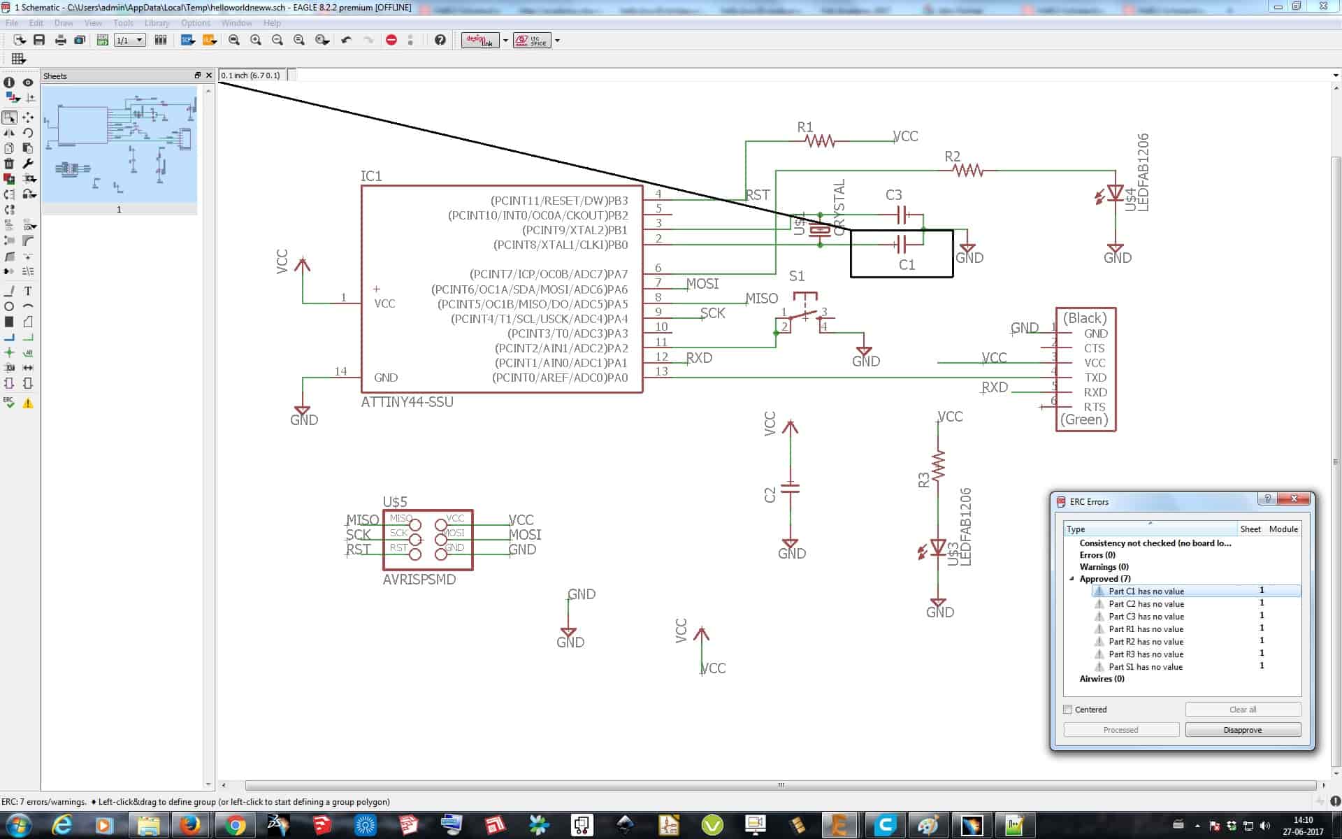
These Errors where because I didn't gave a seperate VCC and GND pins in the Schematics, but I can move forward with it as all the Connections where proper in the circuit diagram.
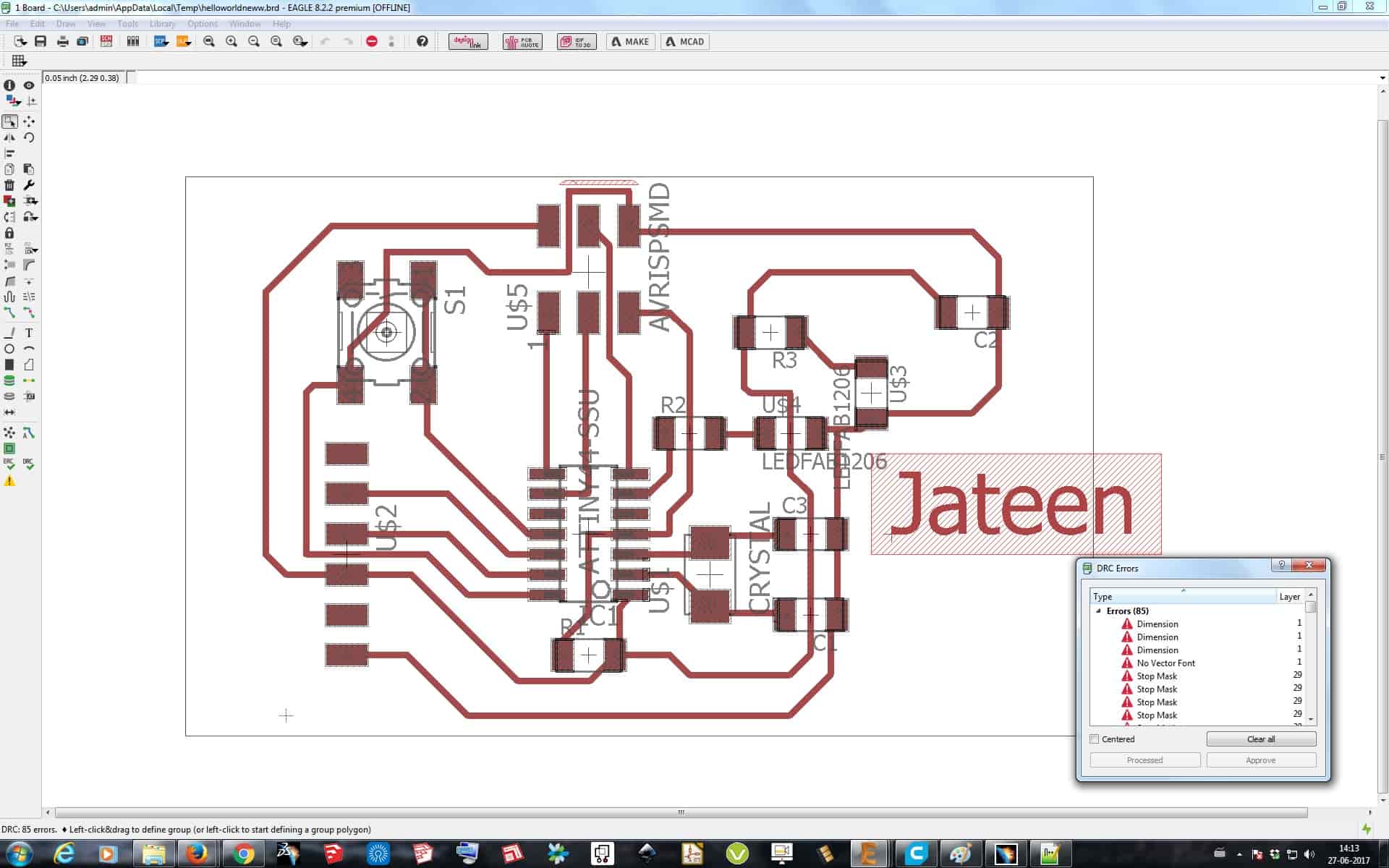
Later I moved to Board File where the board is to be made and after making the board I again did a check but here is known as DRC. The command DRC checks a board against the current set of Design Rules. Only those signal layers that are currently active will be checked, so in order to make sure everything is ok all used signal layers should be active when running the DCR (at least for the final check before manufacturing). Please note that electrically irrelevant objects (wires in packages, rectangles, circles and texts) are not checked against each other for clearance errors. The errors found are displayed as error polygons in the respective layers, and can be browsed through with the ERRORS command. Without parameters the DRC command opens a Design Rules dialog in which the board's Design Rules can be defined, and from which the actual check can be started. If two coordinates are given in the DRC command (or if the Select button is clicked in the Design Rules dialog) all checks will be performed solely in the defined rectangle.
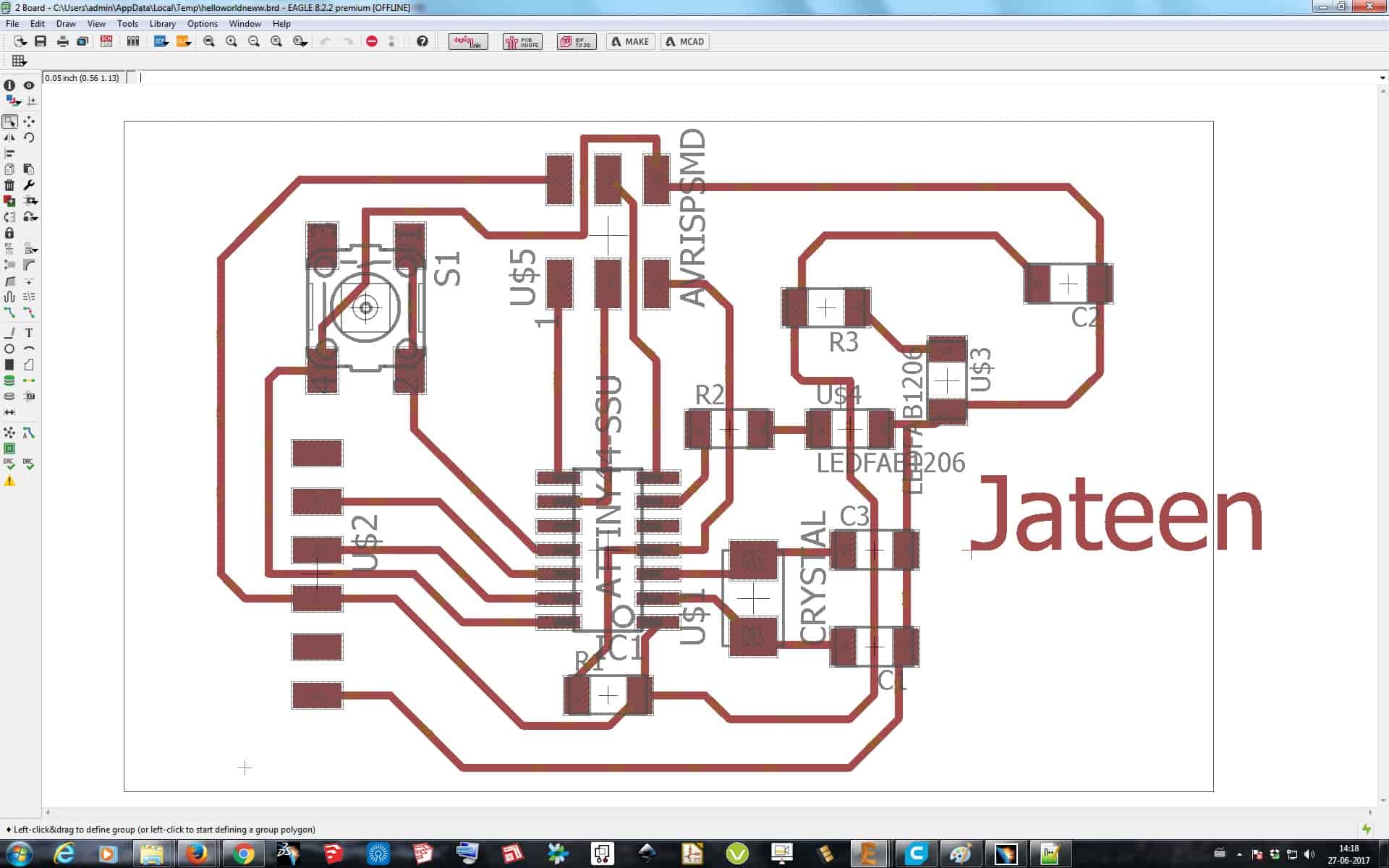
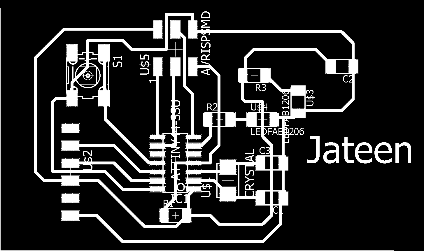
Here as I did the DRC check it showed a number of Errors in its list, but all those errors where because the name got inserted in the Board file, which actually doesn't matter's. So I then converted it to .PNG format and moved to Printing of the board in Modela


After making the file I then wrote my name by simply just entering the text, and then exported it to .PNG format so that I can Mill it on Modela MDX-20.
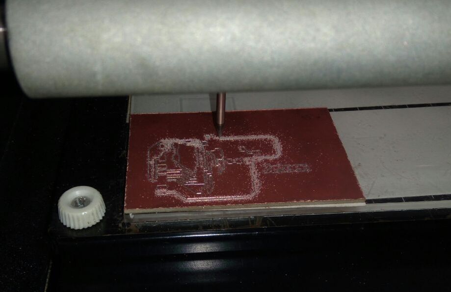

Embedded Programming for working of board